Urbanization is on it's peak and we, as the resident of that particular city, would like to commute as little as possible to our work on daily basis. So the only option that we do have is to accommodate more and more people into as little area as possible and the only ways we can achieve is to either increase the height or increase the depth of the building. But yes, nobody would like to live underground for the rest of their lives. That narrows down to one option and that is to go tall. But there is a problem.!!
Let us say we have about a 10000 sq.ft of land and you are told to design a building. First a 10 story building. You design it quite comfortably for wind as well as seismic you don't see any funny things going on until out building is fairly regular such that it's center of mass and center of rigidity coincides with each other. Now, you are asked to design for 15 story, you still are able to do it but you forces increase and you are looking for sufficient resistance. As you go taller you lateral force and thereby the moments increase in the building quite considerably and you see an effect called overturning. That is you central core wall is trying to topple because it cannot resist such high moments as the moments are huge compared to the axial gravity loads and it topples. Well, that a bad news for any engineers. But wait, we as an engineer have solutions to very problem and if we don't then we find one. To overcome this toppling we use a system called outrigger truss system which helps in reducing the overturning and story drifts. Let me give you a very simple example.
Suppose, you are told to stand on one leg, how hard is it to try to balance on one leg? Gets tough right? It is because the eccentricity of you body's center of mass against the center of resistance and this small eccentricity produce sufficient instability to make you helpless. But one the other hand, you are still standing on one leg with a support on wall using your hand or you use a stick in the other hand and support it on the ground. First try it and then read further..!!
You get a pretty good balance and even if someone pushes it you don't fall or topple. How does this happen? Look at the following picture:

Image 1: Eccentricity between center of rigidity (Center of Resistance) and center of mass causing an unbalanced moment which causes instability in your body and it is hard to balance it out.

Image 2: When you use one of your arm and take a support of vertical pole or stick, you cause an external resisting moment to balance yourself as shown in picture.

Image 3: Many small and slender boats have similar outrigger system which helps it to stay stable even of there is a large disturbing moments caused by moving person.
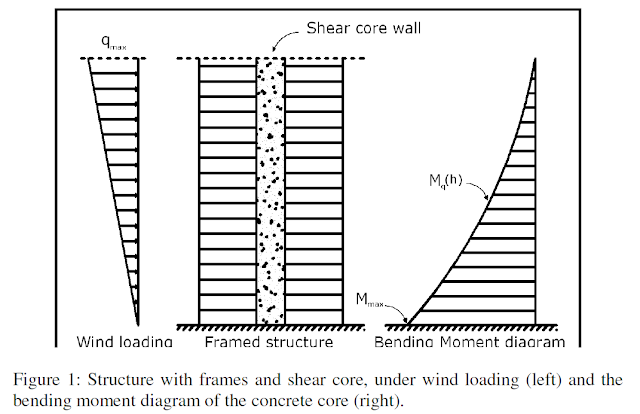


So what happens when the building is narrow and specifically in case of shear wall buildings is that, your core wall is generally located in the center and it gets pretty huge overturning moments either because of wind or earthquake and it kind of acts like the first image that I showed of a person standing on one leg without any support. It is sensitive and unstable. Image shown below shows the amount of forces that a shear wall resists and the behavior of the shear wall under these tremendous forces.

Image 4: Forces due to wind loading on shear wall (Courtesy: Gerasimidis S., Efthymiou E. & Baniotopoulos C. C.)

Image 5: Shear wall deformation mechanism under lateral loading (Courtesy: J. C. D. HOENDERKAMP)
You can clearly see the problems with tall and slender buildings with the overturning moments. Deformation is directly proportional to force acting, deformation is directly proportional to the height of building and force is also proportional to the height of the building. Thus the greater the deformation means higher inter-story and higher displacements and P-Delta effects. All this causes much complex analysis and also we will be increasing the stiffness of the core to resist the deformations and the overturning. This all gets very uneconomical. Today, all the tall buildings even Shanghai tower has shear walls and the forces on such buildings are magnanimous. So in order to take them under control all the buildings have outriggers located at not just one but 2 or 3 different levels. Let me share a picture showing the greater advantage of using an outrigger and how it can help in reducing the thickness of core wall.

Image 6: Reduction in bending moments because of outriggers (Courtesy: Gerasimidis S., Efthymiou E. & Baniotopoulos C. C.)

Image 7: Deformation of building after using outrigger. Notice how the end columns produce a T-C couple to resist the overturning moment. A major factor in reducing forces on core walls (Courtesy: J. C. D. HOENDERKAMP)
This was just a talk about what the outrigger is, but you know it acts as one of the most critical elements in the building if used? Outriggers ,if used, go under a rigorous analysis to make sure that they do not fail. They are a kind of backbone of the shear wall system which helps in force relaxation and if they are not stiff then it would be of no use. You see, if the link that connects the shear wall to the exterior column is flexible, then even if the shear wall deforms it will deform along with the wall instead of transferring the forces to the columns. So whenever you see an outrigger in a building it usually spans up-to one or two story just to capture that effect.
Let me give you some data to support the use of outriggers in reducing the drifts of the buildings.

Image 8: Drift comparison of buildings with and without outriggers
So as you can see, using outriggers not only reduces the drifts in the buildings but also helps in reducing the shear core stiffness. Thus the advantages of the systems are two folds.
The are thousands of buildings using this system and I have mention a couple over here:
1. Shanghai Tower
Shanghai tower is the recently constructed world's one of the tallest building with more than 600 m tall. It has a structural system called mega-frame system which has 8 massive columns in the perimeter and core wall in the center. It has used outriggers to spread out the forces to these 8 mega columns so that the building can take advantage of the T-C couple in the columns. The outrigger system and the core looks something like shown in the picture.

Image 9: Shanghai tower outrigger, core wall and mega frame system (Courtesy: Council of tall buildings and Urban Habitat)
The system developed in the building is simply remarkable and it shows quite rigorous analysis of the building for lateral forces. The model shows every element like meshed core, coupling beams, outrigger trusses, mega columns, belt walls every small thing.

Image 10: Left to right: Shanghai world financial center, Jin Mao tower and Shanghai tower.
2. Taipei 101
Taipei 101 is a 500 m meter tall building and one of the safest places in Taiwan. It has a tuned mass damper at the top of the building but it also has outrigger trusses and mega columns to resist the overturning effects. Again the reason behind its use is the same concept of reducing the forces and controlling the drifts.

If you want to study more about outriggers, go through CTBUH pubications and tall buildings by Taranath. This will give you pertty good insight to outriggers systems.
I hope you like this post and we hope to carry this in much better ways.
Please give your suggestions or comments about our blogs in the comment box below or you can contact us at structualmadness@gmail.com
nice
ReplyDeleteWonderful article!
ReplyDeleteThis comment has been removed by a blog administrator.
ReplyDeleteMervellous explanation.
ReplyDeleteVery nicely explained.Learned concept of outrigger very easily from this article.Thanks
ReplyDeleteAmazing. Please post some blogs on static and dynamic wind analysis.
ReplyDeleteSuperbbbbbb!!!!!!! explanation with the most basic examples. Kudos!!!!